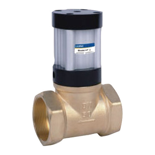
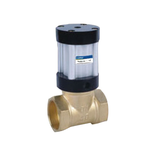
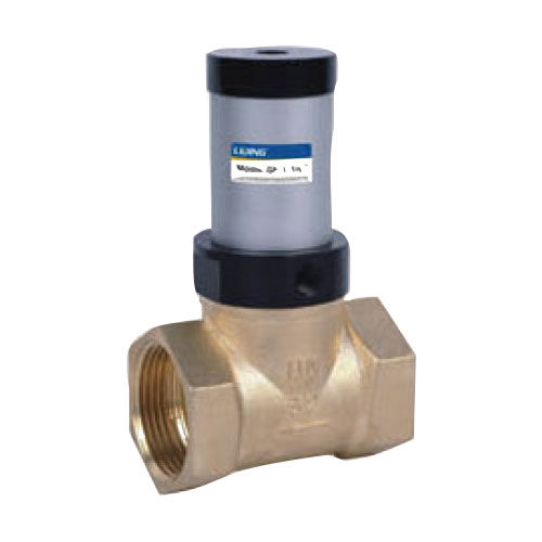
QKGF Series Pneumatic Control Pipe Valve
Product Details
Ordering Code

![]()
Synopsis
Pneumatic control valve is a new type of pneumatic control component designed and manufactured by our company. The valve can be purchased according to the needs of different structural forms such as cut-off type, gate type, return adjustable type and double position adjustable type. It has been widely used in food, packaging, petrochemical, metallurgical, spraying, vehicle and other mechanical equipment. Various structural forms, such as adjustable medium flow, can be selected and purchased according to needs. The use of a wide range of media: suitable for water, oil, gas, pulp and other liquid media.
![]()
Specification
| Model | QKGF-1/2" | QKGF-3/4" | QKGF-1" | QKGF-1 1/4" | QKGF-1 1/2" | QKGF-2" | QKGF-2"F | QKGF-2"II | QKGF-2"A |
| Aperture of Flow Rate | 15 | 20 | 25 | 32 | 40 | 50 | 50 | 50 | 50 |
| Joint Pipe Bore | In = out= G1/8 | ||||||||
| Controling Medium | 40 Micron Filtered Air | ||||||||
| Working Medium | Water. | ||||||||
| Operating Temperature | -40~100℃ | ||||||||
| Controling-Pressure | 0.3~0.7MPa | 0.3~0.9MPa | |||||||
| Working-Pressure | 0~0.7MPa | 0~0.8MPa | |||||||
| Remark | According To The Working Pressure,Equivalent Adjustment Of Control Pressure | ||||||||
![]()
QKGF-2''
QKGF-1 1/2''
QKGF-1 1/4''
QKGF-1''
Inner Constuction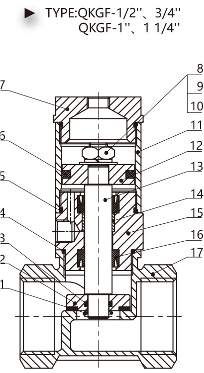
| Serial Numbe |
Name |
| 1 | Pin |
| 2 | Valve Element |
| 3 | Valve Element O-Ring |
| 4 | Valve Body O-Ring |
| 5 | Tube O-Ring |
| 6 | C-Ring Seal |
| 7 | Behind Cover |
| 8 | Nut |
| 9 | Sping Lock Washer |
| 10 | Standard Gasket |
| 11 | Aluminum Cylinder Tube |
| 12 | Piston |
| 13 | Piston Rod |
| 14 | Bearing |
| 15 | Front Cover |
| 16 | Y-Ring Seal |
| 17 | Valve Body |
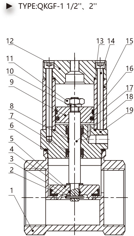
| Serial Numbe |
Name |
| 1 | Valve Body |
| 2 | Pin |
| 3 | Standard Gasket |
| 4 | Valve Element O-Ring |
| 5 | Valve Element |
| 6 | Valve Body O-Ring |
| 7 | Y-Ring Seal |
| 8 | Bearing |
| 9 | Piston |
| 10 | Sping Lock Washer |
| 11 | Nut |
| 12 | Behind Cover |
| 13 | Tube O-Ring |
| 14 | Socket Head Cap Screw |
| 15 | Aluminum Cylinder Tube |
| 16 | Wear-Ring |
| 17 | C-Ring Seal |
| 18 | Piston Rod |
| 19 | Front Cover |
![]()
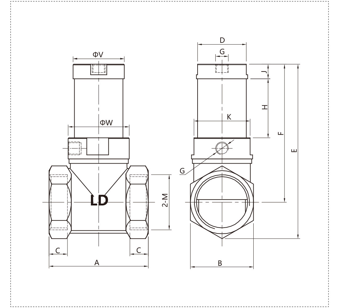
Overall Dimension
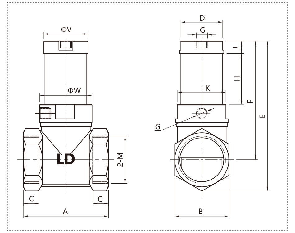
| Mode | A | B | C | D | E | F | G | H | J | K | M | V | W |
| QKGF-1/2" | 47 | 26 | 12 | 24 | 97 | 82 | 1/8" | 34 | 11.5 | 27 | 1/2" | 26 | 29.7 |
| QKGF-3/4" | 54 | 32.5 | 14.5 | 30 | 103 | 84.5 | 1/8" | 34 | 11.5 | 30 | 3/4" | 31.7 | 31.7 |
| QKGF-1" | 62 | 39 | 14 | 37 | 118 | 96 | 1/8" | 39.5 | 11 | 37 | 1" | 39 | 39 |
| QKGF-1 1/4" | 76 | 48 | 14 | 37 | 134 | 108 | 1/8" | 45 | 11 | 45 | 1 1/4" | 39 | 48 |
| QKGF-1 1/2" | 83 | 54 | 18 | - | 162 | 131 | 1/8" | 51.6 | 19 | - | 1 1/2" | 65 | 65 |
| QKGF-2" | 104 | 66 | 22 | - | 178 | 140 | 1/8" | 51.6 | 19 | - | 2 | 65 | 65 |
![]()
QKGF-2''II
Inner Constuction
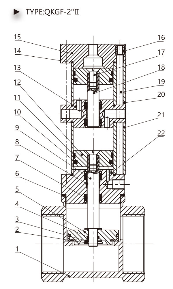
| Serial Numbe |
Name |
| 1 | Valve Body |
| 2 | Pin |
| 3 | Standard Gasket |
| 4 | Valve Element O-Ring |
| 5 | Valve Element |
| 6 | Valve Body O-Ring |
| 7 | Y-Ring Seal |
| 8 | Bearing |
| 9 | Front Piston Rod |
| 10 | ORing Seal |
| 11 | Wear-Ring |
| 12 | Piston |
| 13 | Middle Cover |
| 14 | Tube O-Ring |
| 15 | Behind Cover |
| 16 | Tie Rod Nut |
| 17 | Bolt |
| 18 | Behind Piston Rod |
| 19 | Tie Rod |
| 20 | Behind Cylinder Tube |
| 21 | Front Cylinder Tube |
| 22 | Front Cover |
![]()
Synopsis
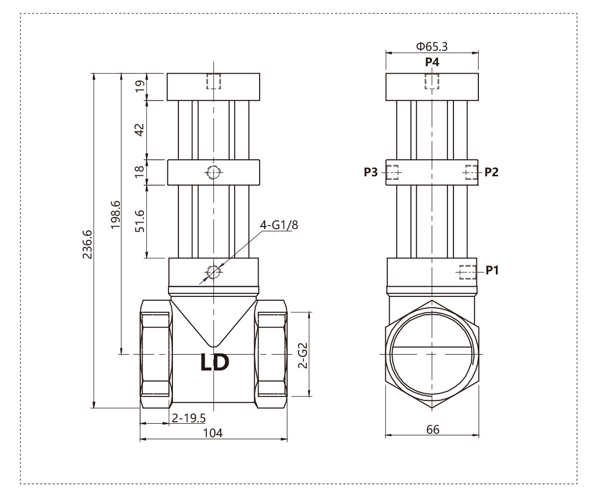
The valve is double position flow adjustable type,when P2 intake, the valve closes: when P1 and P3 intake, the valve opens completely; when P4 intake,the valve opens half.
Note: The intake pressure of P3 and P4 must be more than 0.1 MPa larger than that of P1 and P2 ports in the use process, so that these spools can play a balancing role.
![]()
Overall Dimension
![]()
QKGF-2''F
Inner Constuction
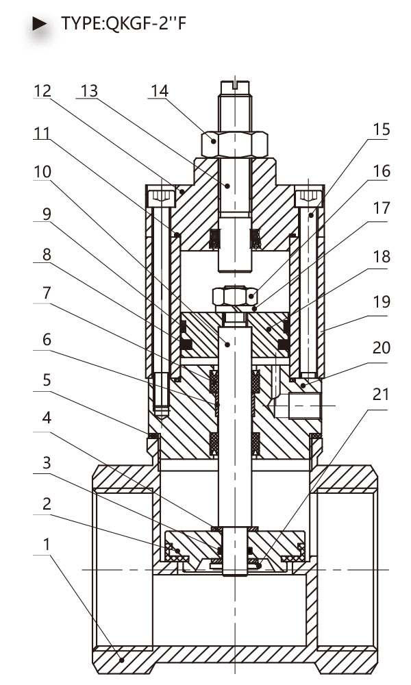
| Seria Numbe |
Name |
| 1 | Valve Body |
| 2 | Valve Element |
| 3 | Valve Element O-Ring |
| 4 | Standard Gasket |
| 5 | Valve Body O-Ring |
| 6 | Bearing |
| 7 | Y-Ring Seal |
| 8 | C-Ring Seal |
| 9 | Wear-Ring |
| 10 | Piston Rod |
| 11 | Tube O-Ring |
| 12 | Front Cover |
| 13 | Adjust Rod |
| 14 | Nut |
| 15 | Socket Head Cap Screw |
| 16 | Nut |
| 17 | Sping Lock Washer |
| 18 | Piston |
| 19 | Aluminum Cylinder Tube |
| 20 | Front Cover |
![]()
Synopsis
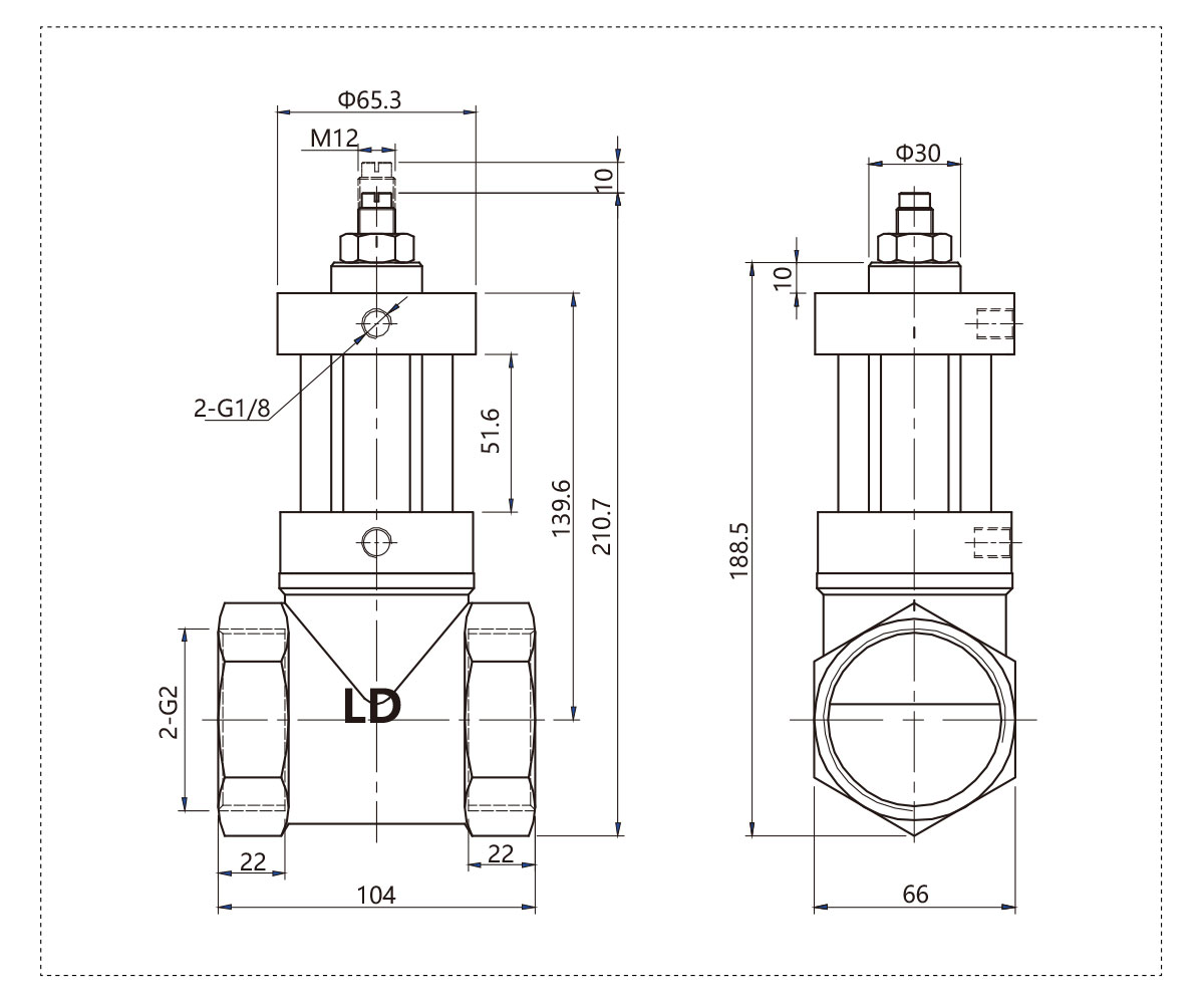
The valve is a return flow adjustable type. The opening height of the valve can be controlled by adjusting the adjusting screw on the back cover to achieve the purpose of regulating the flow.
Note: Nuts must be tightened after the flow regulation is completed to prevent the screw rotation from changing the flow rate.
![]()
Overall Dimension
![]()
QKGF-1 1/4''A
QKGF-2''A
Inner Constuction
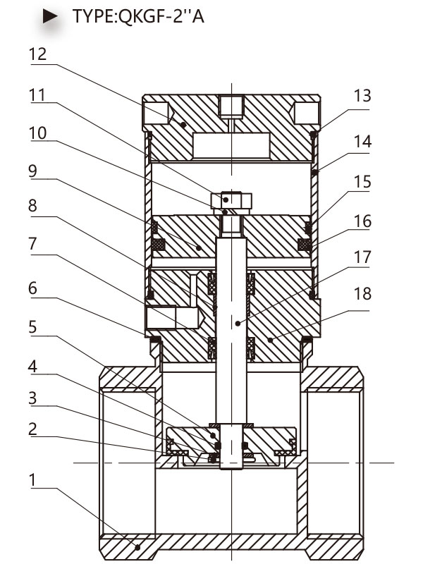
| Serial Numbe |
Name |
| 1 | Valve Body |
| 2 | Pin |
| 3 | Standard Gasket |
| 4 | Valve Element O-Ring |
| 5 | Valve Element |
| 6 | Valve Body O-Ring |
| 7 | Y-Ring Seal |
| 8 | Bearing |
| 9 | Piston |
| 10 | Sping Lock Washer |
| 11 | Nut |
| 12 | Behind Cover |
| 13 | Tube O-Ring |
| 14 | Aluminum Cylinder Tube |
| 15 | Wear-Ring |
| 16 | C-Ring Seal |
| 17 | Piston Rod |
| 18 | Front Cover |
![]()
Synopsis
The valve is a supercharged structure, which achieves the purpose of supercharged by changing the force area of the cylinder in the control part.
Suitable for situations where internal fluid has pressure and sealing requirements.
![]()
Overall Dimension
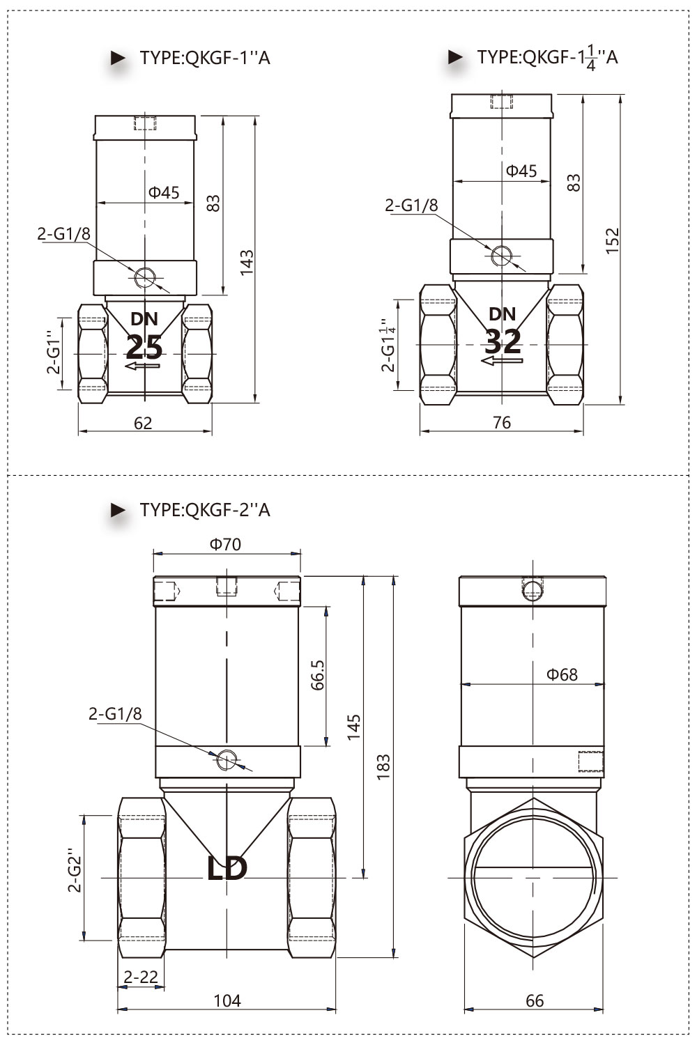
![]()
QKGF-2''S
QKGF-1½ ''S
QKGF-1¼ ''S
QKGF-1''S
Inner Constuction
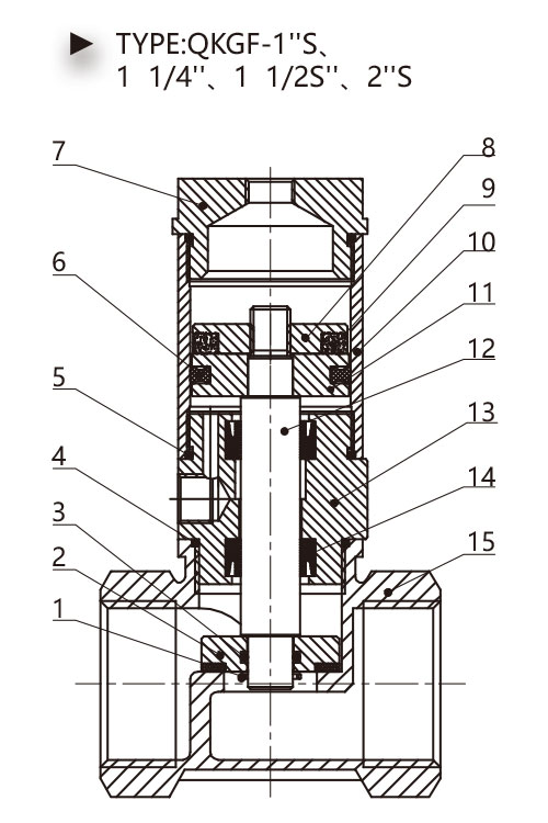
| Seria Numbe |
Name |
| 1 | Pin |
| 2 | Valve Element |
| 3 | Valve Element O-Ring |
| 4 | Valve Body O-Ring |
| 5 | Tube O-Ring |
| 6 | C-Ring Seal |
| 7 | Behind Cover |
| 8 | Magnetic Stator |
| 9 | Magnet |
| 10 | Aluminum Cylinder Tube |
| 11 | Magnet Piston |
| 12 | Piston Rod |
| 13 | Rod Cover |
| 14 | Y-Ring Seal |
| 15 | Valve Body |
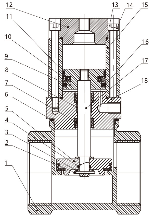
| Serial Numbe |
Name |
| 1 | Valve Body |
| 2 | Pin |
| 3 | Standard Gasket |
| 4 | Valve Element O-Ring |
| 5 | Valve Element |
| 6 | Valve Body O-Ring |
| 7 | Y-Ring Seal |
| 8 | Bearing |
| 9 | Piston |
| 10 | Magnet |
| 11 | Wear-Ring |
| 12 | Behind Cover |
| 13 | Tube O-Ring |
| 14 | Socket Head Cap Screw |
| 15 | Aluminum Cylinder Tube |
| 16 | C-Ring Seal |
| 17 | Piston Rod |
| 18 | Rod Cover |
![]()
Overall Dimension
Our company area has 10000 square and adopted the ISO9001:2015 quality management system certification, the United Kingdom QEC certification and CE certification. As a professional China QKGF Series Pneumatic Control Pipe Valve Suppliers and QKGF Series Pneumatic Control Pipe Valve company,we has participated in the many national standard system revision work like' direction control valve' pneumatic pipe joint test method" and so on. Otherwise, our products have won more than 30 countries registered patents, including 3 invention patents, 20 new utility models. Our QKGF Series Pneumatic Control Pipe Valve are widely used in knitting, medical, food, packaging, petrochemical, metallurgy, coating, vehicles and other mechanical equipment industry.
Recommended Products
Leave Us A Message
What Are You Looking For?


